When the Plan Hits the Floor: Why Tray Parameters Are the Silent Bottleneck in Loading Optimization
1. SCENARIO & PROBLEM
The optimization engine carries out the execution of its spatial calculation routine. The monitoring interface displays a utilization metric approaching ninety-two percent. The solver generates a geometrically coherent stacking sequence. You initiate the distribution of the generated manifest to the warehouse execution team.
Immediate operational friction surfaces.
Material handling personnel report pronounced instability in the upper tiers. The forklift assemblies encounter mechanical interference when attempting to engage the lower deckboards. The rear container door seals strike against overhanging cargo edges during closure attempts. The weighbridge transmits a violation alert concerning the trailing axle capacity.
What triggers the discrepancy?
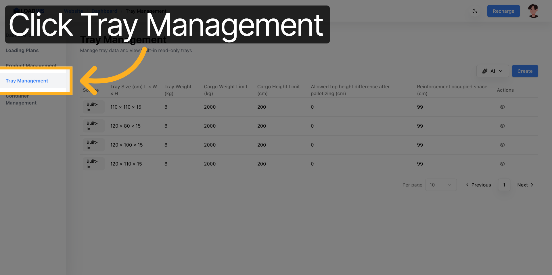
The underlying bin-packing algorithms carried out their mathematical operations without generating a single computational error. The breakdown originates in the foundational parameter dataset. The tray configuration records maintained inside your digital planning environment diverge significantly from the physical timber and polymer structures positioned along the loading bay. Operators frequently omit the self-weight value from the entry fields. That unaccounted mass gradually consumes your designated payload allowance. Planners assign static laboratory load limits that ignore dynamic vibration stressors. The reinforcement clearance parameters receive no data entry. The solver assumes an uninterrupted planar surface for cargo placement. The physical structure dictates a restricted engagement zone. The theoretical optimization scheme encounters immediate rejection upon contacting the facility flooring.
2. WHY IT'S OFTEN UNDERESTIMATED
Teams consistently engage in the practice of regarding pallet assemblies as purely volumetric placeholders rather than structurally complex weight-distribution platforms. They pull generic template files from archived directories. They operate under the assumption that published static load thresholds perfectly align with dynamic transit safety margins. They neglect to account for how a mere one-to-three centimeter reduction in effective edge clearance drastically shrinks the available placement area for upper-tier cartons.
Manual data transcription introduces cumulative fatigue. When an operator engages in the repetitive task of typing dimensional values across several dozen unique pallet classifications, silent degradation inevitably creeps into the dataset. The numbers drift. The tolerances blur. You rarely discover the corruption until the shipping container undergoes staging procedures at the dock edge. The discrepancy hides inside a spreadsheet cell. It waits for physical reality to expose it.


3. KEY OPERATIONS & WHY THEY MATTER
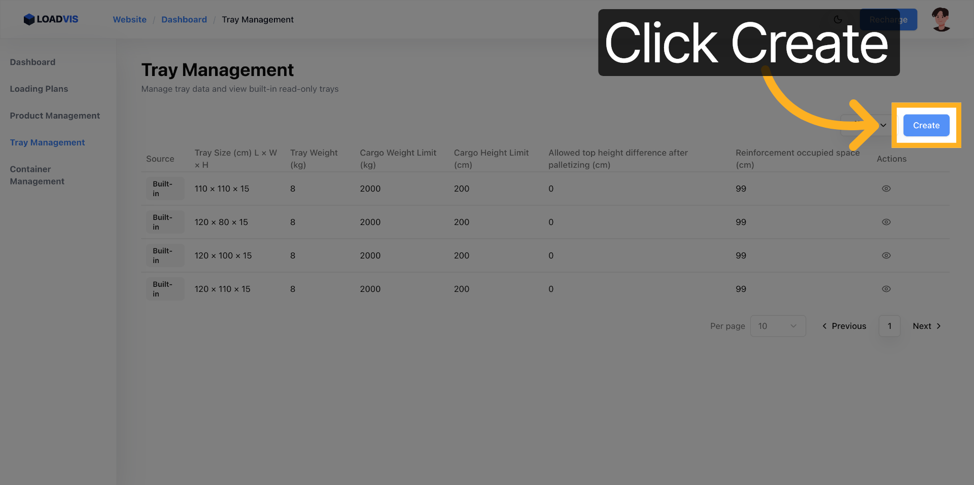
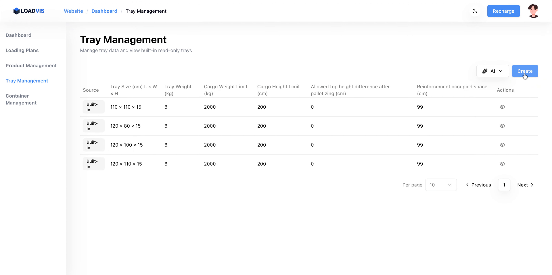
We must carry out a deliberate examination of how specific configuration fields exert direct influence over solver accuracy and physical safety thresholds. The following configuration actions directly determine whether your generated load manifests survive dock-side reality.
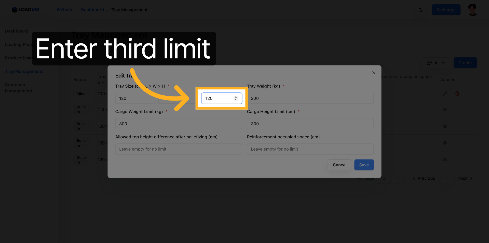
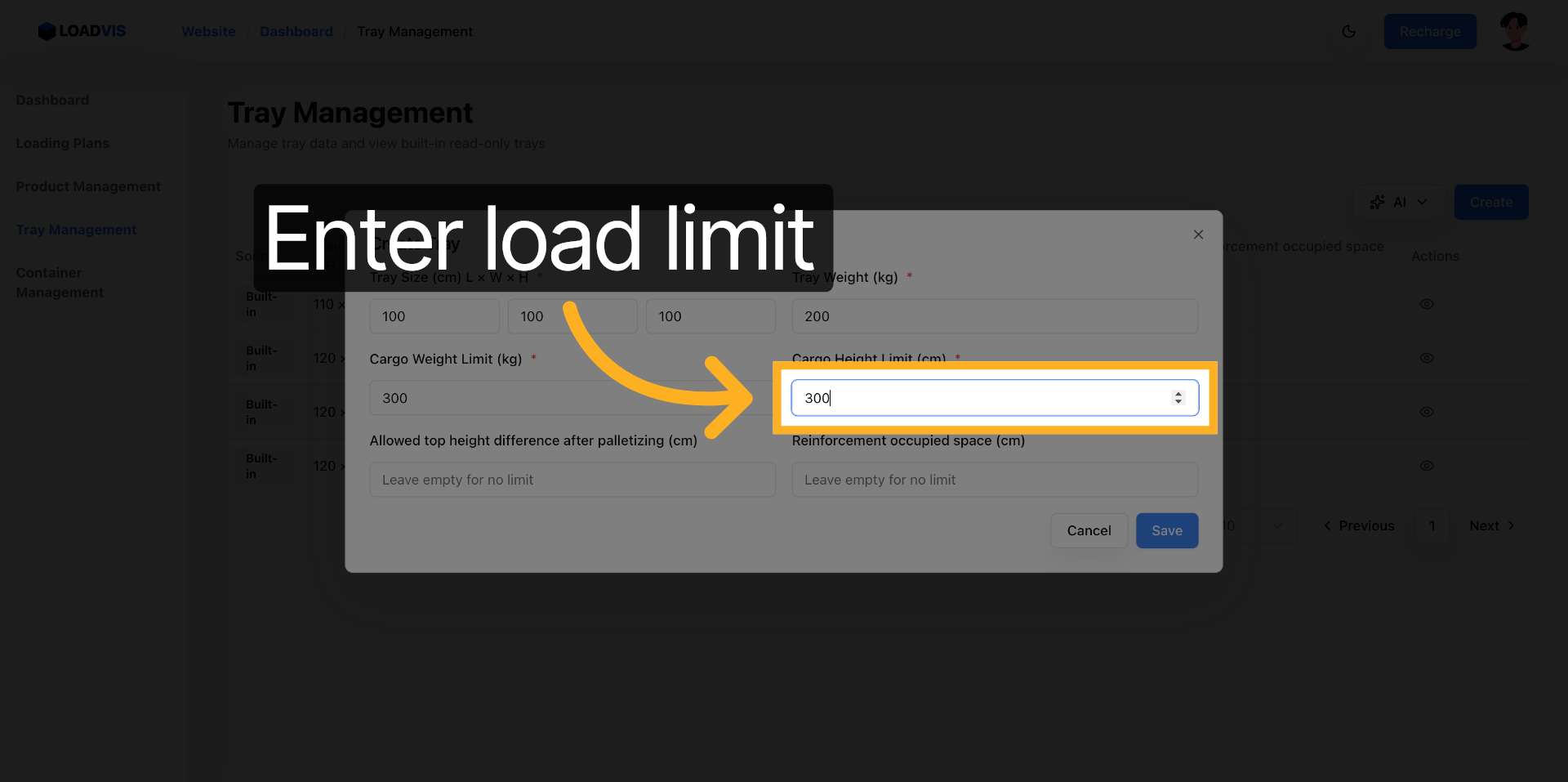
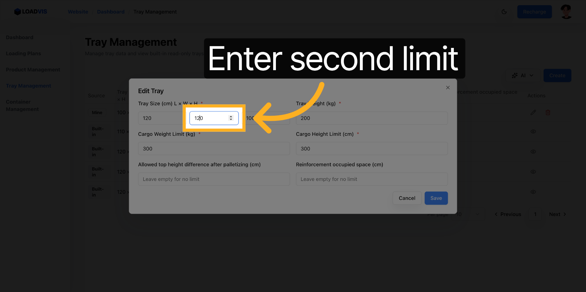
Dimensional measurements alongside their corresponding tolerance bands function as the primary control mechanism for vertical stacking calculations and container aperture verification routines. If a planner neglects the inclusion of a five-centimeter upper clearance buffer during the manual entry phase, the spatial optimizer proceeds to allocate cartons directly into the interference zone. The physical structure scrapes against the door header during the sealing operation. The algorithm assumes clearance exists unless you explicitly state otherwise.
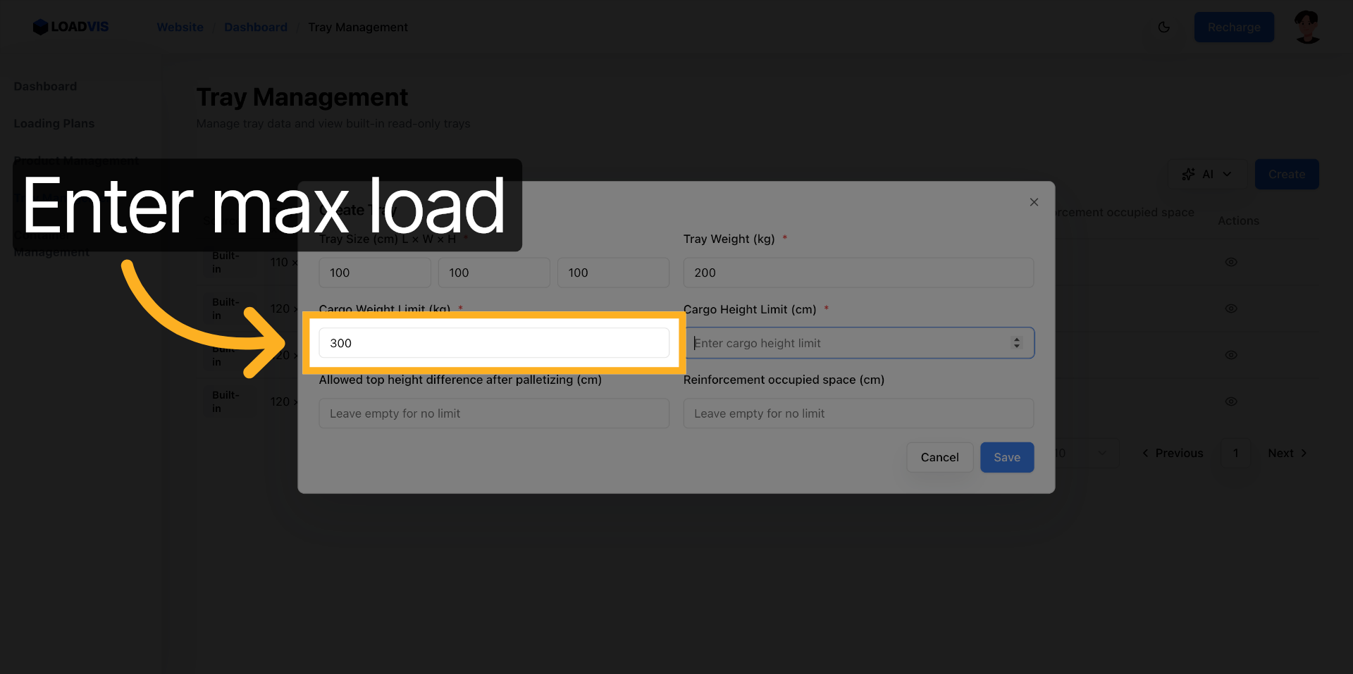
The differentiation between structural self-weight and maximum allowable cargo capacity governs the payload allocation logic. The algorithm carries out the deduction of the base mass from the overall vehicle weight ceiling prior to distributing freight. When you perform the entry of an artificially low self-weight value, the physical transport unit exceeds legal axle thresholds at the weigh station. Conversely, assigning an inflated cargo threshold triggers catastrophic deckboard failure during standard vibration cycles. The solver strictly adheres to your input boundaries.

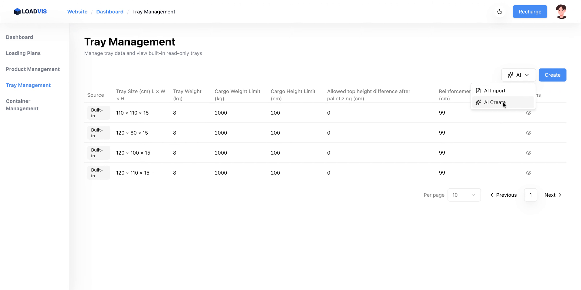
The text parsing engine engages in the conversion of unstructured procurement documentation or informal warehouse notes into precisely mapped database fields. Supplying raw textual inputs allows the system to automatically perform field alignment, thereby eliminating manual transcription fatigue and preventing the common dimensional swap error where length and width coordinates get reversed during hurried data population.
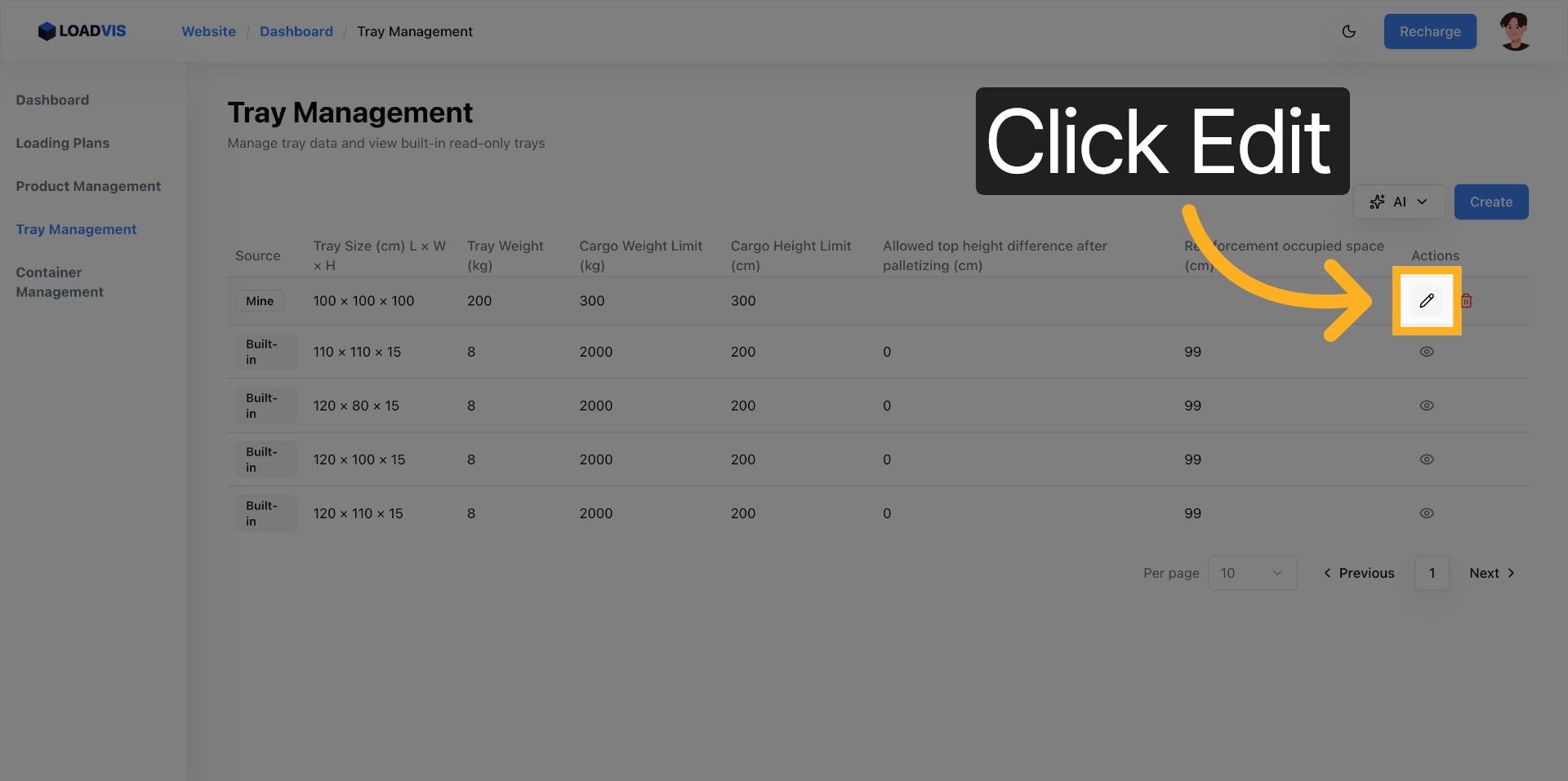
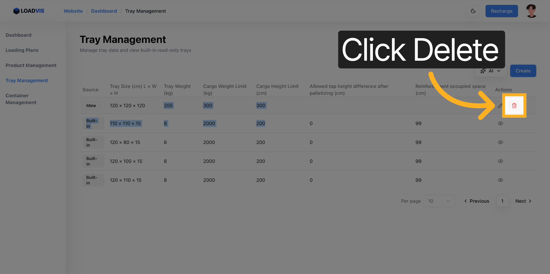
Reinforcement clearance parameters dictate the viable engagement footprint for material handling equipment. Leaving this field in an unconfigured state causes the solver to allocate heavy loads directly above internal structural supports. Physical reality restricts the usable surface to approximately eighty-five percent of the nominal area. The system assumes total availability unless you explicitly provide the measured void dimensions during the editing workflow.

4. WRONG APPROACH VS RELIABLE APPROACH
We observe two distinct operational philosophies.
The conventional approach involves the continuous replication of standardized templates. Operators carry out the manual transcription of fragmented specification details from unreliable memory. They maintain blank clearance configurations while assuming uninterrupted planar loading capacity. They place absolute trust in manufacturer-published static ratings without applying necessary derating factors for humidity degradation, multi-tier dynamic stacking, or transit vibration. The methodology guarantees eventual execution failure. You watch the theoretical utilization percentage climb while the physical stack buckles under lateral shear forces.
A structurally sound methodology requires the direct ingestion of original procurement documentation, verified scale measurement logs, or manufacturer physical labels into the automated text recognition interface. The workflow demands a deliberate post-processing validation sequence. Personnel must engage in the manual verification of base mass values against calibrated scale readouts. Teams must deliberately apply dynamic safety reduction factors to the published cargo thresholds, typically settling at a seventy to eighty percent operational margin of the static rating. You must perform the explicit entry of physically measured reinforcement gaps. Every parameter entry functions as an inviolable constraint boundary rather than an approximate suggestion.

5. HOW FAR THE TOOL CAN HELP & MANUAL CONFIRMATION BOUNDARIES
The software platform excels at carrying out the instantaneous structuring of chaotic textual inputs. The system enforces rigid field mapping protocols and supplies validated constraint boundaries directly into the spatial optimization engine. The solver automatically rejects unattainable stacking elevations. It triggers alerts concerning asymmetric weight distribution hazards. It performs the maximization of usable volumetric capacity while strictly remaining within the defined physical parameters. The interface effectively removes the friction associated with manual form population routines.
The platform cannot, however, perform physical verification of pallet degradation states. The algorithm lacks the capacity to automatically calculate dynamic load reduction curves or to automatically resolve unit consistency conflicts between centimeters, millimeters, kilograms, and pounds. Human operators must carry out manual confirmation procedures across several critical checkpoints. You must physically measure the reinforcement clearance gaps against actual structural components. Planners must manually adjust the maximum cargo load to account for multi-tier environmental exposure. Teams must verify unit alignment prior to initiating the parsing sequence. A final parameter sign-off remains strictly mandatory.
The computational engine respects the numerical input exactly as it receives it. Corrupted data ingestion guarantees unsafe loading output generation. The ultimate judgment responsibility rests upon matching the digital configuration parameters against verified physical floor measurements.
Operational reliability requires unwavering commitment to data integrity. The optimization output remains completely dependent on the precision of your baseline specifications. Garbage parameters produce structurally compromised stacking sequences. Verify your base measurements. Derate for real-world transit conditions. Treat every configuration field as a hard physical limit rather than a negotiable estimate.